


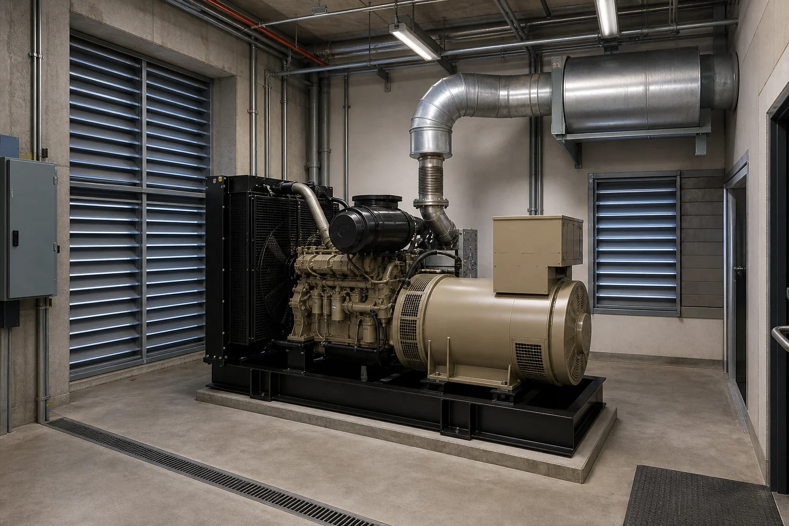



Generator room ventilation is an equipment and building design problem. Opening size alone cannot prove that the radiator, engine and room will receive the airflow they need.
Define the ventilation tasks
A running generator needs air for combustion, airflow through the radiator or remote cooling equipment, and ventilation that removes heat released by the engine, alternator and exhaust system. These duties overlap, but they are not identical. A room may provide enough combustion air while still overheating, or it may stay cool while a restrictive duct prevents the radiator fan from moving its design airflow.
Begin with the offered generator data sheet and application manual. Record radiator airflow, combustion airflow, heat rejected to the room, exhaust flow, maximum allowable radiator restriction and the permitted room or engine inlet temperature. Use the values for the exact rating and cooling arrangement. Similar generator models can have different fans, radiators and restrictions, so generic data should not be carried into final calculations.
Establish the airflow path
A common arrangement brings outdoor air into the alternator end of the room, moves it across the generator and discharges radiator air directly outdoors. The intake should supply both room ventilation and engine combustion. Air should pass through the room without short-circuiting from inlet to outlet or leaving stagnant hot zones around the engine and exhaust.
The actual path depends on the equipment layout. Avoid placing the intake where radiator discharge, engine exhaust, dust, vehicle fumes or another heat source can be drawn back into the room. Consider prevailing wind and nearby walls. A discharge opening that faces a close barrier can create pressure loss and recirculation even when its nominal area looks large.
Calculate pressure loss, not only opening area
Louvers, screens, dampers, silencers, ducts, bends and weather hoods restrict airflow. Their free area is not the same as the wall opening, and two products with the same outer size can have very different resistance. Obtain pressure-loss data from each component supplier at the required airflow. Add the losses through the complete intake and discharge paths, then compare the result with the generator's allowable restriction.
Rules of thumb based on a multiple of radiator area are not reliable enough for final design. They do not capture louver performance, long ducts, acoustic attenuators or wind. A preliminary opening can be used for space planning, but it must remain subject to calculation and equipment selection. If the system is close to the limit, increase the flow area or reduce restrictions rather than assuming the fan will compensate.
Control hot-air recirculation
Radiator discharge air should leave the building without returning around the radiator or through the outdoor intake. A flexible duct connection between the radiator and wall opening can close the gap while allowing generator movement and vibration. The connection and surrounding structure must be designed for temperature, pressure and maintenance access.
Outdoor recirculation also needs review. Keep the discharge away from the intake and account for wind, roof overhangs, courtyards and adjacent equipment. During commissioning, use temperature measurements to check whether inlet temperature rises as the set runs. A stable room temperature does not rule out a local pocket of hot air entering the radiator.
Coordinate exhaust and combustion safety
Engine exhaust must discharge to a safe outdoor location and should not be drawn into the ventilation intake or nearby occupied spaces. Support the exhaust system independently, provide flexible connection at the engine and allow for thermal expansion. Route and insulate hot surfaces according to the project fire and personnel-safety requirements.
A radiator fan often creates slight negative pressure in the room. Other combustion equipment in the same space can be affected, and building doors may become difficult to open if the intake is too restrictive. Coordinate generator ventilation with the building mechanical design. Gas detection, fire protection and local code requirements need project-specific review by qualified designers.
Make the room serviceable
Ventilation equipment should not block routine maintenance. Leave space to clean the radiator, replace belts and filters, remove batteries and reach inspection points. Louvers and screens also need cleaning access. Dust buildup can change system resistance over time, so the maintenance plan should include the airflow components rather than treating them as permanent building fabric.
Automatic dampers must fail or return to a safe operating position when the generator starts. Prove that they reach the fully open position before loading the set, and monitor their status if failure would restrict airflow. In cold climates, controlled recirculation may reduce room cooling during operation, but it must be designed so the generator does not ingest excessive hot air as load increases.
| Check | Design input | Commissioning evidence |
|---|---|---|
| Airflow | Radiator and combustion airflow | Fan path unobstructed at full load |
| Restriction | Loss through louvers, ducts and dampers | Measured static pressure within limit |
| Temperature | Ambient and permitted inlet temperature | Room and radiator inlet readings stable |
| Recirculation | Intake and discharge geometry | No progressive inlet temperature rise |
Commission under representative load
Inspect the complete installation before testing. Confirm damper operation, flexible connections, louver direction, clear openings, exhaust termination and fan rotation. Run the generator at a representative steady load long enough for temperatures to stabilise. Record outdoor temperature, room temperature, radiator inlet temperature, coolant temperature and static pressure where the manufacturer specifies.
Repeat checks with doors in their normal operating position. An open service door can hide an undersized intake. Test alarms, shutdowns and damper interlocks, then document the readings as the baseline for maintenance. If the room exceeds limits, correct the airflow path or restrictions before accepting the installation. Changing alarm settings does not solve the mechanical problem.
- Verify intake and discharge components are fully open.
- Run at representative steady load until readings stabilise.
- Measure room, radiator inlet and outdoor temperatures.
- Measure static pressure at the specified location.
- Check for hot-air and exhaust recirculation.
- Record the final configuration and test results.
Verify the room as a complete airflow path
Fans and openings cannot be checked in isolation. Air must enter the room, pass the heat sources and leave without returning to the intake. Trace that path on the layout and include louvers, screens, dampers, silencers, ducts and weather protection. Each item adds resistance. The equipment supplier or ventilation designer should calculate the combined pressure loss at the required airflow, using the actual components selected for the project.
Check what happens when doors are closed, acoustic elements are installed and the generator operates at the site design condition. Look for short circuits between hot discharge air and the intake, stagnant areas around the engine, and discharge locations that can affect people or nearby equipment. If multiple sets share a room, assess each operating combination rather than assuming all airflow divides evenly.
Commissioning should record room temperature, generator inlet temperature and the condition of dampers and fans at representative load. These readings provide a useful baseline for later maintenance. A rising temperature may point to blocked screens, damaged controls or recirculation before it causes a shutdown.