


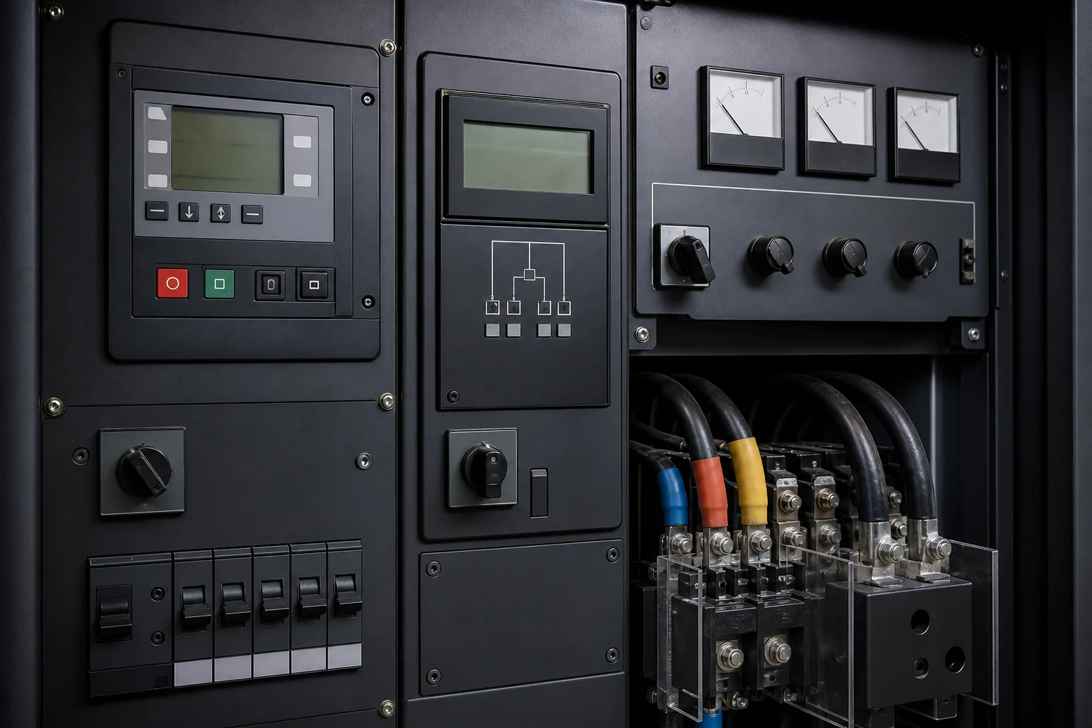



kW and kVA describe different parts of an AC power requirement. A correct generator selection checks both, then tests how the actual load behaves during starting and sudden changes.
The short definition
Kilowatts measure real power. This is the portion of electrical power converted into useful output such as mechanical work, heat or light. Engines are commonly discussed in kW because they must supply real mechanical power to the alternator, after allowing for losses and operating conditions.
Kilovolt-amperes measure apparent power. This combines voltage and current without assuming that they are perfectly in phase. Alternators, cables, transformers and switchgear must carry current, so kVA matters even when part of that current does not produce useful work. A generator must have enough engine capacity for kW and enough alternator capacity for kVA.
Power factor links kW and kVA
For a balanced load under the usual simplified relationship, kW equals kVA multiplied by power factor. Rearranging the formula gives kVA equals kW divided by power factor. If a 400 kW load operates at 0.8 power factor, the apparent power is 500 kVA. This is an illustrative calculation, not a generator recommendation.
Power factor is not a label that can be applied blindly to a whole facility. Heating loads may be close to unity. Motors often operate at a lower power factor, especially when lightly loaded. UPS systems and variable speed drives can present different current waveforms and harmonic content. Use equipment data or measured values where possible, and show which factor has been assumed for each group of loads.
| Real power | Power factor | Calculated apparent power |
|---|---|---|
| 400 kW | 1.0 | 400 kVA |
| 400 kW | 0.9 | 444 kVA |
| 400 kW | 0.8 | 500 kVA |
| 400 kW | 0.7 | 571 kVA |
Why generator nameplates show both
A generator rating may show paired values such as 500 kVA and 400 kW at 0.8 power factor. That pairing describes the offered set under its stated rating conditions. It does not mean every 400 kW load is suitable. The engine may reach its real-power limit while the alternator still has current capacity, or the alternator may reach its kVA or current limit while the engine has spare kW.
Compare offers only after confirming the same duty rating, frequency, voltage and reference conditions. A standby kVA value should not be compared with another supplier's prime kW value. Check whether the alternator is sized for the published set rating or has additional capability for motor starting, harmonics or fault current. The quotation should make the offered engine and alternator combination clear.
Three-phase calculations need the correct inputs
For a balanced three-phase system, apparent power can be calculated from line-to-line voltage, line current and the square root of three. The result must use consistent units. This relationship is useful when a measured current and voltage are available, but it does not replace a load study. Current can change with operating mode, unbalance, harmonic distortion and voltage variation.
Single-phase loads should be identified separately, especially when they may create phase imbalance. A generator serving many single-phase circuits needs the load distributed across phases. One heavily loaded phase can limit the alternator before the three-phase total appears excessive. Ask the electrical designer to provide phase allocation or measured phase currents for an existing installation.
Motor starting changes the picture
A motor can draw several times its normal running current during starting. The exact demand depends on motor design, starting method, driven equipment and the allowed acceleration time. A direct-on-line motor, soft starter and variable speed drive present different conditions. The generator must support the temporary kVA and real-power step while keeping voltage and frequency within limits acceptable to the motor and other connected loads.
Do not add a generic percentage to the running total and assume the motor is covered. Record the largest motors, their starting sequence and whether other loads remain connected. The sizing engineer can then model the transient. Sometimes a staged starting sequence, reduced-voltage starter or load shedding plan can solve the problem more efficiently than a much larger generator.
Non-linear loads need more than power factor
Electronic loads can draw current in pulses rather than a smooth sine wave. The resulting harmonic current can heat the alternator and affect voltage waveform. A conventional displacement power factor does not describe the entire condition. Provide the UPS, drive, charger or rectifier manufacturer, model, input arrangement and harmonic data if available.
Large UPS systems also have operating modes that matter during generator supply. Input current limits, battery charging, bypass operation and staged module connection can change the load. Coordinate generator and UPS settings instead of assuming the utility configuration will behave identically. The same principle applies to variable speed drives and other power electronic equipment.
Prepare a usable sizing brief
For each load, provide running kW, kVA or current, power factor, phase, starting method and operating sequence. Mark uncertain values as unknown rather than filling the schedule with copied assumptions. Separate essential and non-essential loads, then define the worst credible operating case and the largest step. Include voltage, frequency, altitude, ambient temperature and duty.
When the supplier returns a selection, ask for the assumed power factor, calculated running load, largest transient, selected rating and expected voltage and frequency response. This makes the reasoning reviewable. kW and kVA are both necessary, but they are only the opening checks in a complete generator sizing exercise.
- Running kW, kVA or current for each load
- Power factor and phase information
- Motor starting method and sequence
- UPS, drive and rectifier details
- Largest simultaneous load and load step
- Site conditions and operating duty
Check how the load changes during operation
A single total from a load schedule rarely describes the hardest operating condition. Some loads run continuously, some cycle, and others start only during an emergency. Build operating steps that show which equipment is connected together. For each step, record both kW and kVA where the data is available. This exposes a condition with moderate real power but high current, which can otherwise disappear inside a simple total.
Motor starting, transformer energisation, UPS charging and nonlinear electronic loads can affect voltage recovery or alternator selection even when their steady kW looks small. The required information depends on the equipment. Useful records include motor starting method, drive or bypass arrangement, transformer size, UPS topology, charger setting and acceptable voltage or frequency dip. The generator supplier can then check the engine and alternator against the same sequence the site expects to operate.
Keep the calculation assumptions with the load list. State the diversity applied, spare capacity requested and loads excluded from emergency operation. If the project changes, the team can revise the relevant step instead of adding another unexplained margin to the final number.